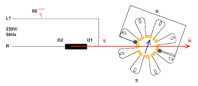
Design of Repulsion Motor
The repulsion motor is the first single-phase AC motor in which the armature field builds up as a consequence of the voltage induced in the rotor. The rotor has the same design as the one in the universal motor – laminated sheet steel with an armature winding inserted into grooves, whose coil ends are connected to the collector segments. The carbon brushes no longer serve to feed current – they are attached on a moveable mount and short-circuited. The stator has no salient pole pieces – the exciter winding is inserted into the grooves of the dynamo steel core.
How the motor works
As was the case in the transformer the current carrying exciter winding
induces a voltage in the coils of the armature winding. The position of
the short-circuited brushes determines the current flow in the armature
winding. If the brushes are aligned with the magnetic poles, the total
current is equal to 0 – no magnetic field can build up in the rotor. The
maximum current flows through the armature winding when the brushes are
rotated by 90° from this alignment. A magnetic field arises whose
direction coincides with the direction of the magnetic field in the
stator. These brush positions are correspondingly defined as the "soft"
and "hard" neutral positions.
Torque, speed and back emf
In order for torque to be exerted on the rotor, the brushes are turned
by 15° out of the "hard" neutral position. Now the north pole of the
rotor is repelled by the north pole of the stator. If the brushes are
turned by 15° in the opposite direction, the rotation direction of the
motor is reversed. At approx. 75% of the rated speed all of the
collector segments are short-circuited with a ring and the brushes are
lifted – their position no longer determines the amplitude of the
armature current. Only the induced back emf is responsible for the
armature current in the short-circuited rotor.


.gif)


working principle of single phase motor i.e repulsion motor is lengthy process but you describe it well thanks for the post.
ReplyDelete