Tuesday, March 5, 2013

Static Mode Operation (Power Transistors)

Static Mode Operation

A power device is working in static mode when dc currents and voltages are applied to its terminals.


The above figure shows the schematic symbols, the terminal names, and the specific currents and voltages for BJT, MOSFET and IGBT.
Bipolar transistors are current controlled devices. In contrast, MOSFETs and IGBTs are voltage-driven devices. The performance characteristics of MOSFETs are generally superior to those of bipolar transistors: significantly faster switching times, higher input impedance, the absence of second breakdown, the ability to be paralleled, simpler drive circuitry.

Power BJT

Bipolar-based power devices include high-power bipolar transistors and Darlington transistors.

The current gain β of power bipolar transistors depends on the collector current IC. When the current increases, the current gain decreases as shown in the above figure.
To raise the current gain, Darlington transistors are used. Darlington transistors consist of two transistors connected in an emitter-follower configuration that share a common collector. The key advantage of the Darlington configuration is that the total current gain of the circuit equals the product of the current gain of both devices.

Power MOS Transistors as Switches

The behavior of enhancement-mode transistors depends on the applied gate-source voltage UGS. The n-MOS transistor is turned-off when UGS is smaller than the threshold voltage UT. There is no current and the device is replaced with an open switch. The inverse diode is inherent to the structure of power MOSFET and ensures a reverse-voltage blocking capability of the device.
When UGS > UT, the transistor is now turned-on. The key to MOSFET operation is the creation of the inversion channel beneath the gate; this allows current to flow. The region between the drain and source can be thought of as a resistor RON, although it does not behave in the same linear manner as a conventional resistor.

IGBT Characteristics

The above figure shows the equivalent circuit and static output I-V characteristics of an IGBT.
An IGBT is in a turn-off state if the gate-emitter voltage UGE is smaller than the threshold voltage UT. When UGE > UT the MOS transistor goes to turn-on. Then, the collector current from the IGBT flows through the series connected emitter-base junction of the PNP transistor, and subsequently through the drain-source channel of the MOS transistor. The output characteristics of IGBT devices are similar to those of MOSFET devices, but due to the series connected junction they are shifted approximately 0.7 V to the right. The output characteristics have two regions – the ohmic region (for small UCE values), and the saturation region (for high UCE values).

Safe Operating Area for BJT (Power Transistors)

Safe Operating Area (SOA) for BJT

The safe operating area (SOA) defines the current and voltage limitations of power devices.


The above figure shows the typical SOA of a power bipolar transistor. It can be partitioned into four regions. The maximum current limit (section a-b) and the maximum voltage limit (d-e) are determined by the technological features and construction of the particular device. The maximum power dissipation limits the product of the transistor's currents and voltages (section b-c). A secondary breakdown (c-d) occurs when high voltages and high currents appear simultaneously when the device is turned off. When this happens, a hot spot is formed and the device fails due to thermal runaway.

SOA for MOSFET & IGBT

The above figure shows the safe operating area (SOA) of MOSFET transistors. This area is bounded by three limits: current limit (section a-b), maximum power dissipation limit (b-c), and the voltage limits (c-d). The SOA of an IGBT is identical to that of the MOSFET SOA.
Since the drain current decreases when the temperature increases in MOSFET transistors, the possibility of secondary breakdown is almost nonexistent. If local heating occurs, the drain current - and consequently the power dissipation - both diminish. This avoids the creation of local hot spots that can cause thermal runaway.

The above figure demonstrates how the SOA of a device increases when the device is operating in pulse mode.
When the device is operating in DC mode the safe operating area is at its smallest. The SOA grows when pulse mode is used. The shorter the pulse signal, the higher the SOA.

Maximum Power Dissipation (Power Transistors)

Maximum Power Dissipation

High currents and voltages in power devices produce very high internal power loss. This loss occurs in the form of heat that must be dissipated; otherwise, the device can be destroyed as a result of overheating.


The maximum power dissipation Pmax indicates a device's maximum capability to transfer and conduct this power loss without overheating.
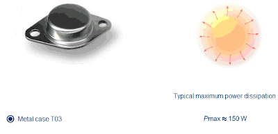
The above figure compares the power dissipation of different devices. As a device type is selected, the circular area changes to show the device's maximum power dissipation. As illustrated in the figure, larger metal cases are more efficient in removing heat from the transistor.

Thermal Resistance

Thermal resistance Rthj-a indicates the ability of the device to conduct and transfer heat from the junction (with temperature Tj) to ambient (with temperature Ta). More resistance means that less heat will dissipate.
The junction-to-ambient thermal resistance Rthj-a consists of two resistances: Rthj-c and Rthc-a in series. The Rthj-c is the junction-to-case thermal resistance. The Rthc-a is the case-to-ambient thermal resistance. The Rthc-a is many times higher than Rthj-c.
The above figure shows the values of Rthj-a for different packages. The particular value of each resistance depends on the type of materials and on the case size. Smaller values are typical for large metal cases.

Maximum Power Dissipation vs. Temperature


The maximum power dissipation Pmax of the transistor depends on the highest junction temperature that will not destroy the device Tjmax, the ambient temperature Ta, and the thermal resistance Rthj-a according to the equation shown in the above figure.
If the ambient temperature is less than or equal to 25°C the device reaches its maximum specified power rating. When the ambient temperature increases, the power rating decreases. If the ambient temperature Ta reaches the maximum junction temperature Tjmax, maximum power Pmax becomes zero.

Heat Sink

One way to increase the power rating of the device is to diminish the thermal resistance Rthj-a. A heat sink, which is usually a metal construction with a large surface area, is used to allow heat to dissipate to ambient more easily.
When a heat sink is present, the global thermal resistance Rthj-a decreases because there are more paths available for heat dissipation. The case-to-heat-sink thermal resistance Rthc-s and the heat-sink-to-ambient thermal resistance Rths-a both facilitate heat dissipation. As a result, the power rating increases as illustrated in the above figure.

Power Transistors

Power Transistors

Introduction


Power Transistors are electronics components that are use for the control and regulation of voltages and currents with high values. They are the basic components for the implementation of linear and switched mode power supplies, motor control circuits, automotive and aerospace systems, home appliances, and energy management systems

Why are Power Transistors Necessary?

Power Transistors are used to produce, convert, control and regulate high amounts of power output.Typical headphone amplifiers have a low output value (just a fraction of a watt). They are usually implemented with standard low power transistors.On the other hand, amplifiers with hundred-watt output power are used to ensure quality sound in large rooms or concert halls. These amplifiers operate with high-level currents and voltages (more than dozens of amperes and volts). The output stages of such amplifiers can be implemented only with power transistors.


Power Transistors are capable of providing high currents and high blocking voltages and therefore, high power. They can be classified into BJT (Bipolar Junction Transistors), MOSFET (Metal Oxide Semiconductor Field Effect Transistors), and devices such as IGBT (Insulated Gate Bipolar Transistors) that combine bipolar and MOS technologies.
The principle of operation behind high power transistors is conceptually the same as bipolar or MOS transistors. The main difference is that the active area of the power devices is distinctly higher, resulting in a much higher current handling capacity. For this reason, they have large packages.

Three Major Device Technologies

The above figure depicts the typical structure of BJT, MOSFET and IGBT devices.
For a BJT to maintain conduction, a high continuous current through the base region is required. This imposes the necessity of high power drive circuits.
MOSFETs and IGBTs are voltage-controlled devices. The IGBT has one more junction than the MOSFET, which allows for a higher blocking voltage but limits the switching frequency. In IGBTs, during conduction, the holes from the collector p+ region are injected into the n- region. The accumulated charge reduces IGBT's on-resistance and thus the collector-to-emitter voltage drop is also reduced.

Monday, February 25, 2013

Three-phase motors in single-phase operation

Three-phase motors in single-phase operation

 
Three-phase motors can also be operated with single-phase alternating voltage. A time shift in the current in one winding strand is normally achieved using an operating capacitor. This in turn causes a magnetic field to be generated. However, due to the capacitor the currents flowing in the windings are not all of equal magnitude. The rotating field is no longer circular but has an elliptical shape. This leads to a considerable drop in power and starting torque.

Two winding motor

Two winding motor Design

Most single-phase induction motors are designed as dual-winding machines. In contrast to single-phase motors there are two separate winding phases built into the stator of the two-phase motor – the power winding and the auxiliary winding. The auxiliary winding is normally disconnected after the motor has successfully started. The auxiliary winding coils are laid between the coils of the power winding. A squirrel-cage rotor is used as a rotor.

Direction of magnetic fields


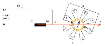
If you connect the main winding to an AC voltage, the motor responds like a transformer with a short-circuited secondary winding. If the rotor had been purely inductive, the magnetic fields in the stator and rotor would have been phase-shifted by 180°. However, due to the fact that the rotor impedance also contains a resistive component, the north pole of the rotor field is always 15° behind the south pole of the stator field. This means that a torque cannot be generated when the motor is switched on.

Types of induction motors with squirrel-cage rotors


The starting torque can be produced with the aid of a rotating magnetic field. The prerequisite for this is a phase-shift between the currents flowing in the working and auxiliary windings which are situated at 90° to one another. The phase-shifted voltage feed of the auxiliary winding can be achieved either through an equivalent resistance, a capacitor or a choke. Depending on the circuitry used for the phase shift, a distinction can be drawn between five different types of two-phased asynchronous motors.

How the motor works

The phase shift between the currents in the two stator windings is achieved in this motor by implementing a considerable amount of active resistance in the auxiliary winding. The auxiliary winding comprises either a larger number of winding turns, lower wire cross-section or is made of resistive material. If the current in the auxiliary winding leads the current in the power winding, the rotation direction is from the pole of the auxiliary winding to the next pole of the power winding. After start-up the auxiliary winding is normally disconnected using a centrifugal switch or a current relay.

Operating characteristics


It is the asymmetrical rotating field which is responsible for the motor's relatively low torque during starting. The starting current amounts to approximately six times the rated current, while the starting torque is about equal to the rated torque. After the auxiliary winding is disconnected, the motor demonstrates the characteristics of single-winding single-phase motors. For that reason such motors are nowadays manufactured exclusively with power levels of under 1 kW and used where they do not need frequent starting.

Capacitro motor with starting capacitor


A capacitor is connected in series with the auxiliary winding. It is selected so that, in phase terms, the current in this winding is ahead of the applied voltage by 40°. The inductance of the power winding is the reason for the fact that current in this winding lags the voltage by 50°. The result of this is a 90° phase shift between the winding currents. When 75% of the nominal speed is reached the auxiliary winding is disconnected from the capacitor. Because the small electrolytic capacitor is only in operation for a few seconds, its value can be chosen to be adequately large – around 200 µF.

Operating response

Capacitor motors with starting capacitors are the most popular single-phase AC motors in use. Their starting characteristics are better than those for motors with resistive auxiliary phase windings. The starting torque is higher, the starting current consumed is lower and the power factor is better. After the auxiliary winding is disconnected, the motor demonstrates the operational characteristics of single-winding single-phase motors.


Sunday, February 24, 2013

Asynchronous motor

Induction motors with squirrel-cage rotors

 
In the repulsion motor the collector and brushes are only used in the starting phase. After a certain speed has been attained the rotor is short-circuited. The next logical step in the simplification of its construction is the short-circuit rotor, usually referred to as a squirrel-cage. The single-phase asynchronous machines have the same simple mechanical design as three-phase motors. A distinction is drawn between single-phase and two-phase motors depending on the number of phase windings.

Design

This motor has a particularly simple and straight-forward design. The laminated stator is equipped with a power winding taking up 2/3 of the grooves. The squirrel-cage consists of two short-circuit rings, which are interconnected by aluminium or copper bars running close beneath the surface of the rotor core. In order to keep power losses low, a deep-bar rotor is not used. The grooves can take a variety of forms.

Direction of the magnetic fields


 If the power winding is connected to an alternating voltage, the motor responds like a transformer with short-circuited secondary winding. There is a 180° phase shift between the magnetic fields in the stator and rotor – the fields oppose each other and there is no starting torque generated when the motor is switched on.

How it works


The pulsating alternating field in the stator can be perceived as two magnetic fields rotating in opposite directions, which at standsill build up two torques of opposite and equal magnitude. The resulting torque is equal to zero. The hand-operated pony motor does not start by itself – it must be cranked in one direction or the other. After start-up, one of the partial moments will predominate so that the resulting torque becomes greater than zero – the motor accelerates until it reaches its rated speed. Here the same regularities and functional principles apply as elaborated on in the section on the repulsion motor.
 

Operating attributes

Compared to other motor types the hand-operated single-phase motor (pony) demonstrates a number of negative characteristics.
Pony motors are only used for small concrete mixers or grinding machines.


Saturday, February 23, 2013

Repulsion Motor

Design of Repulsion Motor


The repulsion motor is the first single-phase AC motor in which the armature field builds up as a consequence of the voltage induced in the rotor. The rotor has the same design as the one in the universal motor – laminated sheet steel with an armature winding inserted into grooves, whose coil ends are connected to the collector segments. The carbon brushes no longer serve to feed current – they are attached on a moveable mount and short-circuited. The stator has no salient pole pieces – the exciter winding is inserted into the grooves of the dynamo steel core.

How the motor works

 
As was the case in the transformer the current carrying exciter winding induces a voltage in the coils of the armature winding. The position of the short-circuited brushes determines the current flow in the armature winding. If the brushes are aligned with the magnetic poles, the total current is equal to 0 – no magnetic field can build up in the rotor. The maximum current flows through the armature winding when the brushes are rotated by 90° from this alignment. A magnetic field arises whose direction coincides with the direction of the magnetic field in the stator. These brush positions are correspondingly defined as the "soft" and "hard" neutral positions.

Torque, speed and back emf

In order for torque to be exerted on the rotor, the brushes are turned by 15° out of the "hard" neutral position. Now the north pole of the rotor is repelled by the north pole of the stator. If the brushes are turned by 15° in the opposite direction, the rotation direction of the motor is reversed. At approx. 75% of the rated speed all of the collector segments are short-circuited with a ring and the brushes are lifted – their position no longer determines the amplitude of the armature current. Only the induced back emf is responsible for the armature current in the short-circuited rotor.

Short-circuit voltage and current

Short-circuit voltage and current

 
The output voltage of the transformer depends on the type of load and on the load current. One measure for voltage change is the short-circuit voltage, which is the voltage that must be applied to the input winding so that it consumes the rated current when the output winding is short-circuited. In transformers with low internal resistance the output voltage only drops off slightly under load. This kind of transformer has a rigid voltage characteristic. Transformers with high short-circuit voltage are called voltage compliant or flexible. Critical for the short-circuit response is the dispersion which differs for various winding arrangements.

Power dissipation and efficiency

 
The efficiency of transformers is specified as the ratio between active power output and absorbed active power. Transformation of electrical energy in real transformers involves power loss. This includes the load-dependent losses in the winding impedance, as well as the voltage and frequency dependent magnetic and eddy current losses arising in the magnetic circuit. The power loss is converted into thermal energy. The iron losses are measured in no-load operation whereas the winding losses are measured in short-circuit experiments.

Friday, February 22, 2013

Operation at no-load and under load

Operation at no-load and under load


Without load the transformer responds like a coil of large inductance. The current consumed by the input winding is the no-load current. The no-load voltage induced at the output is computed according to the primary transformer equation. When operating at no-load almost all of the magnetic flux is concentrated in the iron core. When a load is connected, the load current weakens the input current in accordance with Lenz's law. Some of the lines of flux are then distributed outside the core and this is called leakage flux.

Transformation ratios

In an ideal transformer which achieves 100% power coupling (loss-free) the same magnetic flux permeates both windings. Without load the voltages respond in line with the number of winding turns. The higher to lower voltage ratio is called the transformation ratio. When the transformer is coupled the currents under load respond in inverse ratio to the number of turns. The impedances are carried forward in the square of the transformation ratio. Due to the power losses arising in real transformers these transformation ratios are only approximately correct.

Types of Inductors

Types of Inductors

 
An inductor is basically a coil of wire. The material around which the coil is formed is called the core. Both fixed and variable inductors are classified according to the type of core material used. Three common types are: the air core, the iron core, and the ferrite core. Each has a unique symbol, shown above. Inductors are made in a variety of shapes and sizes. Some are shown above. Small fixed inductors are encapsulated in an insulating material and have the appearance of a small resistor. Variable inductors usually have a screw type adjustment, to allow inductance to be changed. 

Series and Parallel Inductors

When inductors are connected in series, the total inductance, LT, is the sum of the individual inductors. The formula is similar to total resistance in series and total capacitance in parallel.
 

When inductors are connected in parallel the total inductance is less than the smallest inductance. The reciprocal of the total inductance is equal to the sum of the reciprocals of the individual inductances. The formula is similar to the formula for total parallel resistance and total series capacitance.

Thursday, February 21, 2013

Lenz's Law

Lenz's Law

When the current through a coil changes, a voltage is induced. Lenz's Law states that the polarity of the induced voltage always opposes the change in current that caused it. The diagram above illustrates this law. When the switch closes, the current tries to increase, and the magnetic field starts expanding. The expanding magnetic field induces a voltage, which opposes an increase in current. So, at the instant of switching, the current remains the same. When the rate of expansion decreases, the induced voltage decreases, allowing the current to increase. As the current reaches a constant value, there is no induced voltage.  

The diagram illustrates the direction of induced voltage when the current is switched off. In a steady-state condition, the current has a constant value. There is no induced voltage because the magnetic field is unchanging. If the switch is opened, the current tries to reduce, and the magnetic field begins to collapse. At the time of switching, the induced voltage has a direction that prevents any decrease in current. The current remains the same as prior to the switch opening. When the rate of collapse decreases, induced voltage decreases, allowing current to decrease to zero value. 

Wednesday, February 20, 2013

Inductor

Faraday's Law

A permanent magnet has a magnetic field around it, which consists of lines of force, or flux lines Φ, going from the north pole (N) to the south pole (S). Moving a magnet relative to a coil of wire and thus cutting across the flux lines induces a current through the coil.
Faraday's Law states: The induced voltage uind is directly proportional to the rate of change of the magnetic field with respect to the coil and the number of turns in the coil. A coil with more turns (loops), produces a greater voltage. The faster the magnet is moved, the greater the induced voltage.

Basic Inductor


A coil of wire forms a basic inductor. Current through the coil produces an electromagnetic field, which creates a north (N) and a south (S) pole. The more lines of force, the greater the flux, and the stronger the magnetic field.
Constant current has an associated constant magnetic field and there is no induced voltage. An increase in current expands the field. A decrease in current reduces it. As the field expands and collapses with current change, the flux Φ is effectively in motion. Hence, a varying current can produce induced voltage without magnetic motion.

Inductance

 
Inductance is the ability of a conductor to produce induced voltage when the current varies. Conductors that introduce a definite inductance into the circuit are called inductors or coils. The symbol for inductance is L, and the unit is the Henry (H). The inductance is one Henry when the current, changing at the rate of 1A per second, induces 1V across the coil.
An inductor stores energy in the magnetic field created by the current. The energy stored is proportional to the inductance and the square of the current. The energy is supplied by the voltage source that produces the current.

More Detail about Inductor

Tuesday, February 19, 2013

RC Circuit

Series RC Circuit

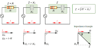
In a series RC circuit, the current is the same through both the resistor and capacitor. Thus, the resistor voltage (UR) is in phase with the current (I), and the capacitor voltage (UC) lags the current by 90o. Therefore, there is a phase difference of 90o between UR and UC as shown above. From Kirchoff's voltage law, the sum of the voltage drops must equal the source voltage, Us. Since UR and UC are 90o out of phase, the magnitude of the source voltage can be expressed by using the Pythagorean theorem, as shown in the diagram.

Capacitive Impedance


The impedance Z of an RC circuit is the complete opposite to sinusoidal current. Its unit is the ohm. The phase angle is the phase difference between the total current and the source voltage. In a purely resistive circuit, the impedance is equal to total resistance. The phase angle is zero. In a purely capacitive circuit, the impedance is the total capacitive reactance. The phase angle is 90o, with the current leading the voltage. The impedance, Z, of a series RC circuit, depends on both the R and the C reactance values. It is determined by the impedance triangle shown. The phase angle is between zero and 90o.

ZC Frequency Dependence


Capacitance reactance Xc varies inversely with frequency. Impedance Z changes in the same way as Xc. Therefore, in RC circuits, Z is inversely related to frequency. The diagram illustrates how Z and Xc change with frequency, with the source voltage held at a constant value. As the frequency increases, Xc decreases. Less voltage is dropped across the capacitor since Uc = I Xc. Also, Z decreases as Xc decreases, causing the current to increase. An increase in I causes more voltage across R as UR = IR


Analysis of RC Circuit

Analysis of Series RC Circuit

 
Ohm's Law and Kirchoff's Law are used in the analysis of a series RC circuit. Ohm's Law, when applied to a series RC circuit, involves the use of quantities of Z, U, and I. The three equivalent forms of Ohm's Law are shown above. From Kirchoff's voltage law, the sum of the voltage drops equals the source voltage (Us). Since UR and UC are 90o out of phase, the magnitude of the source voltage is expressed by the voltage triangle as shown in the illustration.  

Analysis of Parallel RC Circuit

 
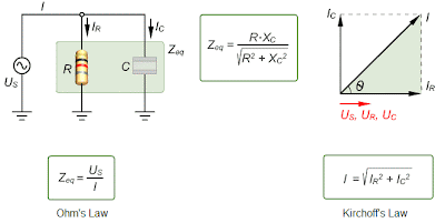
The source voltage appears across both the resistive and the capacitive branches. Therefore, Us, UR and Uc are all in phase and of the same magnitude. In a parallel circuit, each branch has its individual current. The resistive branch current IR is in phase with Us, but the capacitive branch current Ic leads Us by 90o. By Kirchoff's current law, the total current is the phasor sum of the two branch currents. The impedance of a parallel circuit equals the applied voltage divided by the total current Zeq = Us / I


Monday, February 18, 2013

Capacitors in DC Circuit

Capacitors in DC Circuit (Charging)

Charging and discharging are the main effects of capacitors. A capacitor charges when it is connected to a DC voltage source through a resistor. Initially, when the switch is open, there is no voltage flowing across the capacitor's plate. When the switch is closed, the current jumps to its maximum value, and the capacitor begins to charge. As the charging process continues, the current decreases, and the voltage across the capacitor increases until it equals the source voltage. When the capacitor is fully charged, there is no current. A capacitor blocks constant DC. A capacitor charges following a nonlinear curve as shown above.

Capacitors in DC Circuit (Discharging)

The capacitor discharges when a conducting path is provided across the plates without any applied voltage. A capacitor can serve as a voltage source, temporarily, by producing a discharge current. When the switch is closed, the capacitor begins to discharge. Initially, the current jumps to a maximum. The direction of the current during discharge is opposite to that of the charging current. During discharging, the current and capacitor voltages decrease. When the capacitor has fully discharged, the current and the capacitor voltage are zero. The discharging curve is shown in the illustration above.  

RC Time Constant


A certain time is required for the capacitor to fully charge or discharge. The rate at which the capacitor charges or discharges is determined by the RC time constant of the circuit. It is symbolized by Greek letter τ (Tau), where τ = RC. When R is increased, the charging current is reduced, thus increasing the charging time of the capacitor. When C is increased, the amount of charge increases, thus, more time is required to charge capacitor for the same current. In one time constant, the capacitor voltage changes approximately 63%. It reaches its final value at approximately 5τ.