Series RC Circuit
In a
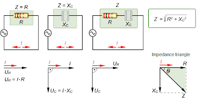
series RC circuit, the
current is the
same through both the resistor and capacitor. Thus, the resistor voltage (
UR) is in phase with the current (
I), and the capacitor voltage (
UC) lags the current by 90
o. Therefore, there is a phase difference of 90
o between
UR and
UC as shown above. From Kirchoff's voltage law, the sum of the voltage drops must equal the source voltage,
Us. Since
UR and
UC are 90
o out of phase, the magnitude of the source voltage can be expressed by using the Pythagorean theorem, as shown in the diagram.
Capacitive Impedance
The
impedance Z of an
RC circuit is the complete opposite to sinusoidal current. Its unit is the ohm. The
phase angle
is the phase difference between the total current and the source
voltage. In a purely resistive circuit, the impedance is equal to total
resistance. The phase angle is zero. In a purely capacitive circuit, the
impedance is the total capacitive reactance. The phase angle is 90
o, with the current leading the voltage. The impedance, Z, of a series
RC circuit, depends on both the
R and the
C reactance values. It is determined by the
impedance triangle shown. The phase angle is between zero and 90
o.
ZC Frequency Dependence
Capacitance reactance Xc varies inversely with frequency. Impedance Z changes in the same way as Xc. Therefore, in RC circuits, Z is inversely related to frequency. The diagram illustrates how Z and Xc change with frequency, with the source voltage held at a constant value. As the frequency increases, Xc decreases. Less voltage is dropped across the capacitor since Uc = I Xc. Also, Z decreases as Xc decreases, causing the current to increase. An increase in I causes more voltage across R as UR = IR


.gif)
.gif)


 Ceramic Capacitor
 Plastic-film Capacitor
 Tantalum capacitors
 Aluminum Capacitor